
This is an old revision of the document!
Why?
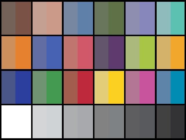
Why do the color correction at all? A picture is worth a thousand words so here's a visual to demonstrate the original (left) and color-corrected (right) values:
Support
SUB2r camera starts supporting CCM (a.k.a. CMX) with FX3 v. 58 and FPGA v. 73.
3x3 -> 4x4
Industry papers on CCM use a \(3x3\) matrix yet we do a full \(4x4\) so there needs to be a way to convert from one to another (and also from an RGGB into BGGR ordering). Here's an article on Math StackExchange on that subject.
And if you'd like to play with the values in an Excel-like environment - here's a link to Google Sheets for your enjoyment.
Pixel layout
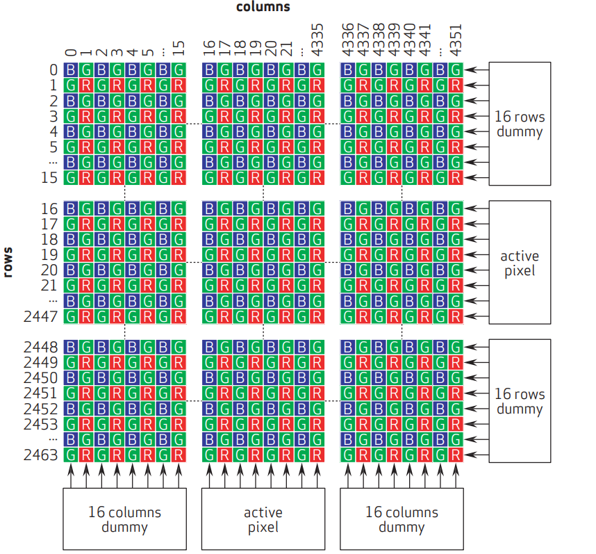
With the OV10823 OmniVision image sensor we use the “standard” Bayer pattern that looks like this:
CCM
Color Correction Matrix is often used as an “add-on” matrix during YUV→RGB conversion. In our case, since the de-bayering and RGB→YUV conversions happen literally on opposite sides of the imaging pipeline, we only use the portion of the corrections designed to compensate for the sensor's cross-talk, converting pre-debayer values \(R_0, Gr_0, Gb_0, B_0\) into \(R, Gr, Gb, B\) that are then used for conversion into RGB:
\[ \begin{bmatrix} B & Gb & Gr & R\end{bmatrix} = \begin{bmatrix} CCM_{00} & CCM_{01} & CCM_{02} & CCM_{03} \\ CCM_{10} & CCM_{11} & CCM_{12} & CCM_{13} \\ CCM_{20} & CCM_{21} & CCM_{22} & CCM_{23} \\ CCM_{30} & CCM_{31} & CCM_{32} & CCM_{33} \end{bmatrix} \cdot \begin{bmatrix} B_0 \\ Gb_0 \\ Gr_0 \\ R_0 \end{bmatrix} \]
In this matrix \(Gb_0\) is a value of a “green pixel in a blue row” (i.e. in a B-G-B-G-B-… row) and, similarly, \(Gr_0\) is a value of a “green pixel in a red row”.
The matrix is applied to a \(2\times2\) block of \(\begin{bmatrix}B_0 & Gb_0 \\ Gr_0 & R_0\end{bmatrix}\) values represented by a “flattened out” vector \(\begin{bmatrix}B_0 & Gb_0 & Gr_0 & R_0\end{bmatrix}\) to produce the same \(2\times2\) block of corrected values \(\begin{bmatrix}B & Gb \\ Gr & R\end{bmatrix}\).