This is an old revision of the document!
SUB2r control center
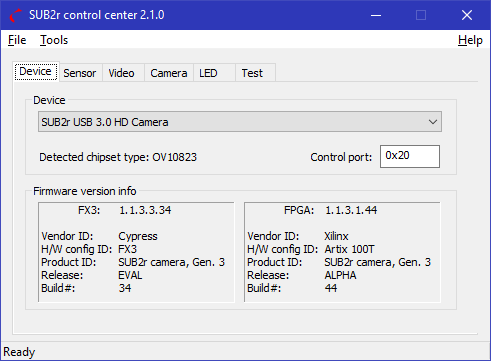
SUB2r control center, a.k.a. “frankie”, a.k.a. “frankie whisperer” is SUB2r's utility to access pretty much all the internal features of the SUB2r camera. The tool can be run independently and concurrently with any other software on the system, including the apps that stream video, as it, itself, doesn't do video streaming and thus is not locking access to the camera.
It is possible to run multiple copies of “frankie” on the same host, even if you only have a single SUB2r camera attached/connected.
The tool has additional functionality when it is run in an “Expert mode” (set in Preferences), in which case its main window looks like this, with extra tabs and menu items:
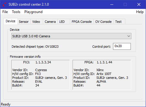
The rest of this article describes the full functionality, as available in that “Expert mode”.
The main window consists of the following tabs:
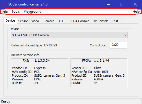
The menu gives access to these additional functions:
- File: Open/Save/Save As... and Exit commands
Main window with tabs
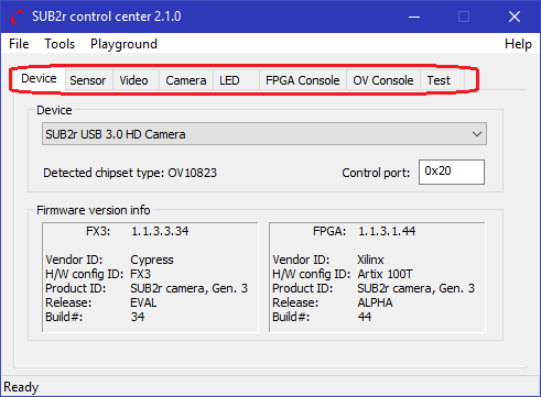
The most often used functions are easily accessible on the main window as tabs. each tab is (generally) independent of others and doesn't rely on any state in any of the other tabs. The only obvious exception is the first, Device tab, which specifies the device to control.
As you select a tab its state is refreshed from the values in the camera. When running multiple copies of “frankie” and performing operations that change the state of the camera and then switching to another copy of the tool, you may need to select a different tab, then back to the tab you had opened, for the values to be refreshed.
Non-critical error message and notifications are displayed briefly at the bottom of that window on a status bar.
Device
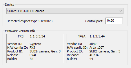
The Device 1) you select in this tab is used throughout the rest of this tool.
When running more than one SUB2r camera attached to your host the camera names will be augmented to include a number. That number is system-wide unique, however it is likely to change if you change the USB topography 2).
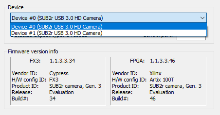
If, for whatever reason, the device is not responsive - it will be marked as “offline” and a warning message will let you know that using such device may lead to extended time delays and unresponsive UI. Currently the communication timeout is hard-coded to 10 seconds.
Once the camera is selected, its sensor's chipset type and model is autodetected and presented next to Detected chipset type. The default Control port is 0x203) and should generally never be changed for normal operations.
Further down the page a Firmware version info is presented for the 2 other crucial camera components: FX3 and FPGA. There's a direct and unambiguous correlation between the numeric version (e.g. 1.1.3.3.29) and the text that follows. For more info refer to FX3 version info and FPGA version info respectively.
Sensor
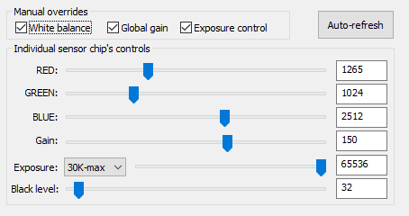
Sensor tab provides access to some of the video-config related functionality that is implemented on the image sensor chip itself. That means that the adjustments that are made here are performed before the image is converted to 8-bit per channel format. Depending on the specific sensor these adjustments are done while the image is still in its raw 10-bit or 12-bit per channel format.
Not all the sensors support all the presented functions, notably the Global gain and Exposure control are permanently enabled on all the supported sensors except the old OV 9714 one.
The Auto-refresh button is useful for those times when you have either more than one “frankie” up and would like to see the values reflected in an inactive window, or if you'd like to monitor the changes in those values made by a source that is external to the tool4).
All the settings on this tab are sensor-specific and the exact same number (say Exposure) will almost definitely mean different exposure timing when used on different types/models of image sensors, even when those are from the same manufacturer(!).
RED, GREEN, and BLUE individual channel gains are applied (additive) to the red/green/blue channel values, respectively. In case of overflow the value is clipped at the max limit, e.g. 1024 for a 10-bit format.
Gain, a.k.a. “global gain” is applied (additive) universally to all the 3 channels.
It is worth mentioning that increasing the Gain (either global or per-channel) always adds noise. There are many types of noise that are inherent in CMOS image sensors. The value of a pixel is derived by the number photons collected by the pixel over a given time. There is even noise from the light source. A CMOS pixel will generate dark current noise, which is an electrical charge generated in the absence of photons. Conversion of photons to an electrical current is known as the Quantum Effect, the process of which will also generate noise. Gain is analogous to volume in audio. Turning the volume up will make your music louder, but it will also amplify the “hiss” or white noise in the background. The same is true for color channel or global gain. It will increase the intensity of the color, but it will also increase the noise. To optimize the signal to noise ratio, it is always advantageous to increase exposure first before pushing Gain.
Exposure is a sensor-defined number that doesn't have an easy-to-describe way of being converted into exposure timing without taking into consideration internal sensor's characteristics (like a current internal clock speed, or sub-windowing, or an externally-driven global shutter) and is beyond the scope of this document5).
Due to Exposure having such a wide range of values and the need to sometimes fine-tune the value with the slider, we have split the range into 4 overlapping sub-ranges with values 0-9K, 6-18K, 14-35K, and 30K-max.
Black level is, quite possibly, the least understood adjustment that an image sensor can utilize. In the simplest form this is a threshold value below which any value is considered to be black. Increasing it a little can “bring more light” into the picture, but going too far will make that picture look “washed out”.
Video
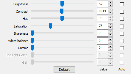
These are the “standard” video attributes users have gotten accustomed to over the years. They utilize the USB Video Class (UVC) spec6) to control a pre-defined set of video parameters.
It is important to note that the adjustments listed in this section are applied to the image after it has been re-sampled to 8-bit per channel color format (or an equivalent for non-RGB formats) so these adjustments are more coarse than as if they were made on the sensor chipset itself. That is the reason the Gain remains not implemented for the UVC in SUB2r camera :)
Those attributes that are not advertised by the camera as supported are grayed out. The list of supported attributes depends on the code running on camera's board and is likely to expand with time.
Currently this tab doesn't support any of the SUB2r's UVC extensions.
Camera
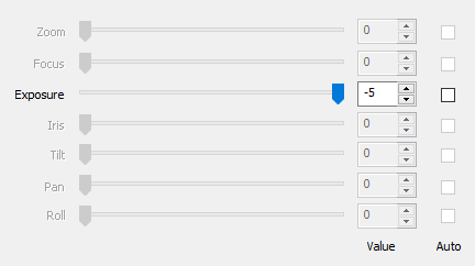
Much like the previous Video tab the Camera tab provides access to a set of standard parameters defined by UVC spec for camera control. Most of these require independently powered modules of one kind or another (think power-zoom or auto-focus) and are not part of the initial camera release.
LED
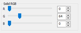
The LED tab is currently more like a toy and provides a way to quickly test if camera is responding to commands.
The front-facing LED can be programmed to emit colors in 8-bit 3-channel RGB color space (24 bits total), though due to technical limitations some of the colors cannot be presented accurately - which is something only people with an exceptional color perception would ever notice.
The design is currently utilizing a CREE 3 element LED part number CLVBA-FKA-CAEDH8BBB7a363.
Dominant Wavelength
Red     619-624nm
Green   520-540nm
Blue    460-480nm
Luminous Intensity (mcd) @IF=20mA
Red     224-560
Green   280-900
Blue     90-355
The LED is mounted on the camerboard. There is a BIVAR PLPC combination light pipe and diffuser mounted on the front plate inline with the LED. The light pipe helps to reduce the perceived intensity and increases the viewing angle.
N.B. Using very high values produces an intensely bright color that may be uncomfortable to look at directly, especially in a dim environment.
FPGA Console
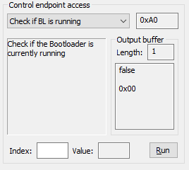
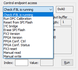
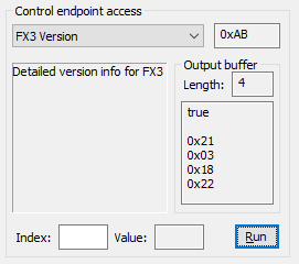
The FPGA Console tab is for advanced users and allows to manually access registers and issue some commands to the camera's FPGA.
Select a command from the drop-down list, modify (if necessary) the control endpoint, for some commands specify Index and for write commands specify the Value, for read commands specify the return buffer size (in 8-bit bytes), then click Run and see the results of the execution in the output window where the first line is a true/false return code followed by byte-by-byte hexadecimal representation of the returned buffer.
When entering numbers the standard C-style prefixes are valid:
0xfor hexadecimal numbers0for octal- no prefix - depends on the settings and is decimal by default
All the listed below commands and those not listed in here are documented on this page: FX3 HVCI and FPGA I²C commands.
Check if BL is running
Run this command with no parameters to see if the Bootloader is currently running. Almost always the answer to that question is (expectedly): “Bootloader is not running”.
Run DPC Calibration
This forces the FPGA to perform calibration for DPC7). Obviously to perform this operation the camera's lens must be physically blocked by an opaque cap to make sure no light hits the image sensor.
Set the DPC Threshold in Value field. Valid range for this parameter is [0..255]. The higher the number the fewer pixels will be considered defective. Setting the threshold too low will result in too many pixels satisfying the “defective” criteria.
Total number of remembered “defective” pixels is limited to 65536.
Generally you are way better off using a provided GUI for the same operation, described in the section DPC calibration further down.
Reset from SPI Flash
Writing anything into this location causes the FPGA to reconfigure itself from the SPI Flash.
I²C bridge
This is a gateway command that facilitates access to additional commands. For more information see FPGA I²C commands.
Command's “offset” is specified in the Index field and a value to be written (for write commands) in the Value field.
Erase SPI Flash
Any write to this location invalidates the FX3 SPI Flash and causes FX3 to reset to a bootloader mode for reprogramming.
FX3 Version
Takes no parameters, returns 4 bytes that represent the FX3's detailed version information. Documented here: FX3 version info.
FPGA Version
Similar to FX3 Version this command takes no parameters and returns 4 bytes of an encoded version information for FPGA. See FPGA version info for details.
FPGA Conf. Ctrl
Any write to this location will put the FPGA into configuration mode. Only a reset of the FX3 and FPGA will restore normal operation.
FPGA Conf. Status
This will read the current configuration status, described here: FX3 host vendor command reference.
FX3 reset
Cypress Vendor Command to reset the FX3
Manual read/write
These allow you to specify all the parameters manually and “fire at will”. Needless to say that if you are playing with this aimlessly you can brick the device. Yes, this will void the warranty.
OV Console
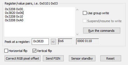
Accessing image sensor's 4096 internal registers is fun, especially if you know what you are doing and if you have the documentation available.
N.B. Some of the internal registers are write-once while toying with others can render the image sensor non-functional and un-repairable.
All the input numbers on this page, unless explicitly prefixed with either 0x or 0, are interpreted as decimal, unless specified otherwise in Preferences.
Code input window
That large white text input space is where you enter white-space separated pairs of numbers. The first number in a pair is the register to write into and the second is the value to write. All the registers are 8-bit. Pressing the Run the commands button will blindly execute all the writes in a quick succession start to end, regardless of potential errors - be those errors misprinted numbers or communication issues.
Use group write
Checked by default causes all the listed pairs to be batched up into a single group write. Disable if you are controlling the group write yourself (like in the displayed example).
Suspend/resume to write
Pause the video stream for the duration of the updates. Currently disabled due to unresolved technical difficulties.
Peek at register
Quick peek at a particular register. A new read request is sent any time a value in that window is updated (even as you type). To force-update the view hit the little arrow button and both hexadecimal and binary representation of the value in specified register will be updated.
Image flip
Perform a simple image flip, horizontally or vertically (or both).
Correct RGB pixel offset
When you flip the image the resulting RGGB pattern gets broken and the color reconstruction fails, producing quite unexpected results. Hitting that button will attempt to properly offset the beginning of the image to restore the proper functionality. This is not needed for some image sensors that don't break the RGGB pattern when flipping the image (like OV 10823, for example).
Send FSIN
If your camera is set to be synchronized off of an external source8) pushing that button will set it into mode where it will process frames only at the request of that external synchronization signal and not off of its internal rolling shutter.
Sensor standby
Temporarily suspend the video feed, mostly used when you need to update multiple registers and want to make the operation “atomic”.
Reset
Try to perform a soft reset of the image sensor.
Test
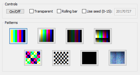
OmniVision image sensors come with a set of internal on-chip test modes which can be enabled with controls on this tab.
| Control | Function |
|---|---|
On/Off | Turns the internal test patterns on or off |
Transparent | Makes the test pattern alpha-blend with the actual video stream |
Rolling bar | Produces a rolling bar effect - a horizontal dark line moving across the image |
Use seed | Make pseudo-random patterns repeatable by specifying a seed value9). Not every image sensor supports this |
Patterns | Chose a pattern you'd like to see |
Menu items


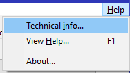
File
Besides the self-explanatory Exit options this File menu provides the ability to save/load a subset of the camera's state parameters which provides an easy way to clone the settings or to save/restore presets for various sets of environment: per lighting equipment/setup, indoor/outdoor, bright/dim, etc
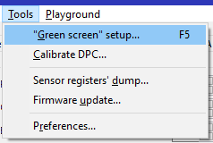
Color Substitution - ''Green screen'' setup
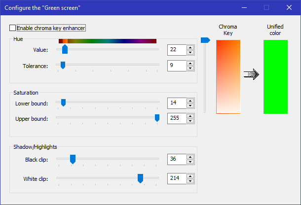
One of the most exciting out-of-the-box features of the camera is its color substitution Green Screen enhancer. Given a range of colors the camera will automatically replace them with a set “flat” color on the fly, making it extremely robust to actually use the image substitution techniques during your streaming!
Enable chroma key enhancer
Enable/disable the pre-processing of the image during which pixels with values in a range of colors are substituted with pixels of a given uniform “flat” color.
Chroma Key
The color to substitute is specified as a Hue value and an angular Tolerance, ±° (both ways, positive and negative symmetrically). If the color meets the required Saturation threshold, it will be substituted with the color shown in the Unified color rectangle.
The slider to the left of Chroma Key preview box allows you to see the key colors in various degrees of brightness.
To pick a color from a screen just click on the Chroma Key window and (while keeping the left mouse button down) move the cursor over the pixel you are interested in. Once you let the left mouse button go the new Chroma Key will be set on the camera.
Saturation and Shadow/Highlights limits
Pair of sliders in these 2 sections allow you to limit the lower and upper values of what to consider to be a color to replace. This way you can exclude the colors that are way too washed out (low Saturation) or that are too bright (high White clip) and only substitute the colors you are actually interested in.
Unified color
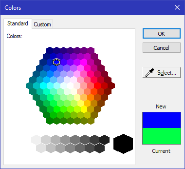
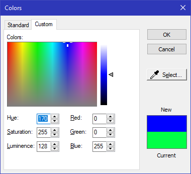
To change the replacement Unified color click on the color box - this will bring the OS's built-in color picker UI.
You can specify the color to replace with either by using one of the standard Windows colors or by explicitly defining a color either via its HSL or RGB triplet of values.
DPC - Defective Pixel Calibration
With literally millions of individual sensor elements, each measuring in mere microns, running at ultra-high clock speeds, it is virtually inevitable to have errors10). Some errors are more annoying (read: visually noticeable) than others and random pixels with bright values fall squarely into that category.
Many factors can introduce those sporadic fluctuations, even the rarely thought about ones like a very benign heating of the sensor's elements. The pixel performance will also change over time.
During power cycle the SUB2r camera performs auto-calibration and tries to figure out which pixels “misbehave”. This is also known as PRNU or pixel response non-uniformity. For best results the camera cap has to be fully closed which (naturally) is rarely the case in its day-to-day use.
To that end a function is provided that allows to perform the re-calibration without power cycling the camera. Video streaming has to be stopped for the calibration to be done properly.
First, set the desired Threshold. The higher the value, the fewer pixels will be detected.
Detecting too many pixels may degrade the final image quality as it will result in a (though relatively tiny) loss of details.
There's a limit of a total of 65536 detected pixels.
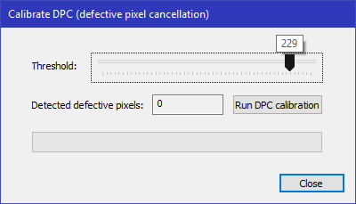
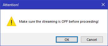
Once the Threshold is set click the Run DPC calibration button, which will immediately get disabled to prevent double-clicking, and wait for the process to complete. A dialog box pops up to remind you that you must only do the calibration when NOT STREAMING. Not even previewing:
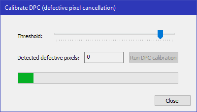
The calibration itself usually takes a few seconds.
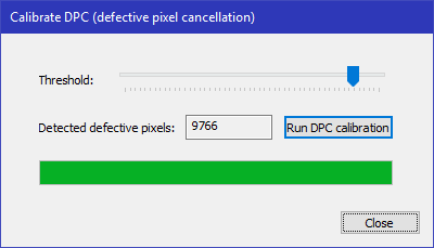
Once the calibration is finished a new Detected defective pixels total will be displayed so you can judge whether the result is acceptable to you.
Prior to de-Bayering or demosaicing, the conversion of RGGB to RGB, the processor will replace the value of a known defective pixel with the average value of the previous and subsequent pixel of the same color by row. In the case of R1,G1,R2,G2,R3,G3,R4,G4,R5,G5 if G3 is determined to be a defective pixel, then G3 will be replaced by the value of (G1+G4)/2.
NOTE: The OVT10823 sensor is a native 4K chip which is down sampled by binning and skipping method to 1080p. Currently a separate DPC is required for 4K and 1080p.
Sensor registers' dump
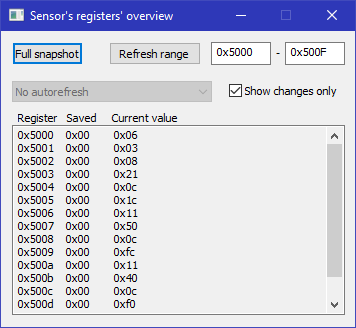
When debugging or just monitoring the image sensor directly one might need to see which values are changing between two points in time. This little handy window provides you the ability to take a snapshot of the current register values in a range of addresses and then, at a later time, Refresh range to see what's the current state. Or, if you have the Show changes only enabled it will just show what's changed.
Clicking either Full snapshot or specifying too wide of a range of addresses could cause the sensor chip to timeout and become unresponsive. Powercycling the camera should bring it back to life 
Firmware update

Once the camera is in your hands that doesn't mean we've stopped improving it. On the contrary - the development continues with lots of new and exciting features in the pipeline. This dialog box provides a way for you to install newer versions of the firmware onto your SUB2r camera (or downgrade to earlier version, if needed).
The main Firmware upgrade for DX3 and FPGA dialog box provided current version info for both the FX3 and the FPGA (these two modules run different code, of course).
For either one you could chose to pick up only the code that is “at least in X development cycle”, where “X” ranges from Alpha to Bugfix and defaults to whatever you set in Preferences, like Evaluation. You can also chose to use a Local file if you build your own binaries with your custom functionality:

Unless you are using a local file an active internet connection is required to get the firmware upgrade images from the server.
Once you select the desired earliest release cycle you are presented with the available image files, sorted from the most recent to the oldest one:

Once you click on Upgrade firmware button a new modal dialog box pops up to show the progress:
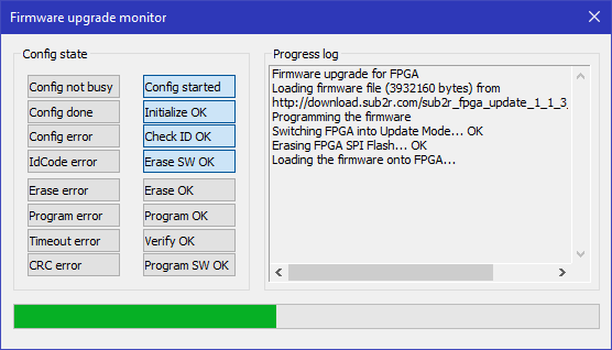
The panel to the left displays the current state of the configuration bits and the right panel lists actions that are performed. The progress bar at the bottom shows an approximate completion of the firmware upgrade operation.
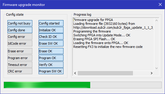
Once the process is done the window will stay auto-close in 30 seconds unless the user closes it before then.
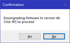
Trying to upgrade to the exact same (or older) version of the code will ask for an explicit confirmation from the user:
FUBAR scenario
In an unlikely event that something goes wrong (e.g. power outtage during the upgrade) the camera will automatically reset back to its factory “Golden image” from which you can proceed with the firmware upgrade as described above in this section.
Preferences
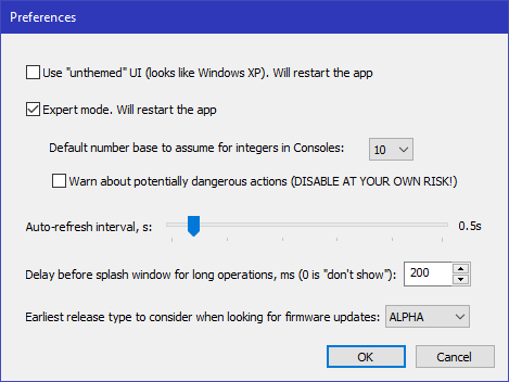
All these preferences are saved in the Windows' Registry and are retained between the tool's uninstall/re-install cycles. The registry key where they are all stored is:
\HKCU\Software\SUB2r\Webcam tools\SUB2r camera control center
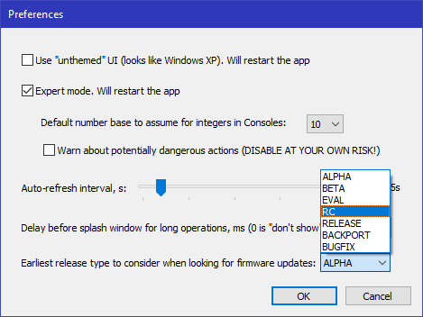
Before we get to the full list of options here are 2 more screenshots showing the values in drop-down boxes:

- Use “unthemed” UI - provides look and feel of the older, XP-style UI
- Expert mode: allows access to additional functionality and opportunity to brick the camera if you don't know what you are doing
- I (personally11)) prefer to write numbers in hex when programming the registers, so this setting saves me some typing when I change it to
16:P - If you are feeling particularly confident (or adventurous) you can disable the “are you sure?” warning popup when running unsafe commands. You will be asked again (ONE LAST TIME!) and then you are on your own - the warranty doesn't cover damage caused by using the tool in this manner
- Auto-refresh interval is used, for example, in the
Sensortab for monitoring some of the changes in image sensor's registers when enabling theAuto-refresh - Whenever a single command or a batch of commands takes longer than this specified amount of time a
Meditating…dialog box pops up to show progress: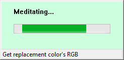
- When upgrading firmware you can change the earliest release cycle to consider for your new image. Normally you are going to be just fine with the default
Release candidatesetting, but if you are an early adopter you might want to change that toEvaluationor even earlier than that. As always - the earlier the code is in a release cycle, the more risk there is that it would have bugs and other unintended behavior.
Technical Info
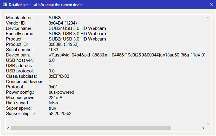
This window presents technical information related to the currently selected Device. As this is a text area you can select and copy this information as plain text.
View Help
Selecting that View Help… menu item or hitting an F1 key would bring you to this manual 
About
A bit of self-explanatory text not unlike what you find in pretty much every piece of software in the world.
The Version information includes the date and time of the build12) in the following format: YYMMDD_hhmm and uses a 24-hour clock.
Device is defined as reported by the OS and doesn't necessarily correspond 1-to-1 with the physical object connected to the host. I.e. a single SUB2r camera may report a video imaging device, an audio in and an audio out devices, and an FX3 device for the Cypress bridge0x6c port, however for chipset auto-detection the tool will still try the 0x6c port if the default 0x20 fails to respond within the timeout periodExposure value is interpreted in the context of the currently selected video mode (resolution, windowing, FPS) and may additionally depend on other bit modes set in other registers. For all these reasons the number presented for Exposure is just that - an abstract number in a range, supported by the sensor chip.DPC - defective pixel cancellation20170727 number was put in on 2017/07/27 and was meant to be updated with every new version but that has been replaced with a different method which automatically embeds the build date/time into executableGMT time zone